Advanced Multicopter Position Control Tuning
The objective of this document is to give an overview of the higher-level position-control tuning parameters for multicopters. Higher-level tuning applies to any parameter that has an effect on the desired position/velocity setpoint as opposed to lower-level tuning that influences the tracking. The set of higher-level tuning parameters can be split into two sections: tunig parameters for manual control position mode and tuning parameter for auto. Some parameters will have an effect on both modes.
This guide is for advanced users/experts.
Short Background
The position controller consists of an outer P-position control loop and an inner PID-velocity control loop. Depending on the control mode either the velocity control loop only is active or both. For the remaining part of this tutorial the term position-control represents the position and velocity control loop activated and velocity-control when just the velocity control loop is in use.
Precondition
Before doing any higher-level related control tuning, please follow first the instruction PID-tuning. It is not recommended to use the advanced position control tuning parameters as a fix for bad tracking or vibration.
Manual Position Control Mode
In manual control mode the stick inputs are mapped either to position-control or velocity-control. Position-control is active when the stick inputs are within the deadzone MPC_HOLD_DZ and velocity control otherwise. All the parameters below are tuning parameters and cannot be mapped directly to the physical quantity.
MPC_ACC_HOR_MAX
This parameter is used for position-control in the horizontal direction, where the vehicle is supposed to stay at current location. The limit for velocity setpoint change is defined by
MPC_ACC_HOR_MAX. This parameter should be set larger than any of the other acceleration related parameter in the horizontal direction.
MPC_ACC_HOR and MPC_DEC_HOR_SLOW
In velocity-control the rate limit for velocity setpoint is extracted from a linear map from stick input to acceleration limit with maximum MPC_ACC_HOR and minimum MPC_DEC_HOR_SLOW. For example, if the stick input
is at MPC_HOLD_DZ, the limiting acceleration is MPC_DEC_HOR_SLOW, if the stick input is at maximum (=1), the the limiting acceleration is MPC_ACC_HOR and any stick input in between is mapped linearly between the two parameters.
In addition, MPC_DEC_HOR_SLOW also limits the change in velocity setpoint when the user demands a deceleration in the current flight direction. For instance, if the stick input changes from maximum (=1) to 0.5, the velocity
setpoint change will be limited by MPC_DEC_HOR_SLOW.
During transition from velocity-control to position-control, there is a hard switch from from MPC_ACC_HOR to MPC_ACC_HOR_MAX and a reset of the velocity setpoint to the current vehicle velocity. The reset and the hard witch can
both introduce a jerky flight performance during stopping. Nonetheless, The reset is required because the
smoothing parameters introduce a delay to the setpoint, which can lead to unexpected flight maneuvers. A simle example is given below:
 .
.
The example fligth is as follow: the user demands full speed from hover followed by a stop request. This is equivalent to full stick input with maximum value of 1 followed by zero stick input. To simplify the example, let's assume
that MPC_ACC_HOR_MAX is equal to MPC_ACC_HOR and therefore there is no hard switch in acceleration limit when switching from velocity-control to position-control. In addition, let's assume the maximum speed that can be demanded is 4 m/s.
During full stick input, the velocity setpoint will not change directly from 0 m/s to 4 m/s (aka step input). but rather the velocity setpoint follows
a ramp with slope MPC_ACC_HOR. The actual velocity of the vehicle, however, will not track the setpoint perfectly, but rather will lack behind. The lack will be more significant the larger the value of MPC_ACC_HOR.
Without the reset (the top graph), at the moment of the stop demand (stick equal 0) the velocity setpoint will ramp down with the maximum rate given by MPC_ACC_HOR_MAX. Due to the lack the vehicle will first continue to accelerate in the direction previous
to the stop demand followed by slowyly decelerating towards zero. With the reset of the velocity setpoint to the current velocity, the delay due to the lack during stop demand can be overcome.
MPC_ACC_UP_MAX and MPC_ACC_DOWN_MAX
MPC_ACC_UP_MAX >= MPC_ACC_DOWN_MAX, otherwise the firmware will overwrite the given values.
- position-control: the limit in velocity setpoint change in z-direction is given by
MPC_ACC_UP_MAX. - velocity-control: the limit in velocity setpoint change for stick input is
MPC_ACC_UP_MAXfor upward andMPC_ACC_DOWN_MAXfor downward direction.
MPC_JERK_MAX and MPC_JERK_MIN
These two parameters only have effect during the transition from velocity-control to position-control. The purpose of these two parameters are to minimize the jerk introduced from forward flight to hover (please see MPC_ACC_HOR and MPC_DEC_HOR_SLOW).
The jerk-parameter controls the rate limit with which the acceleration limit can change to MPC_ACC_HOR_MAX. The actual jerk-value is a linear map from velcity speed to jerk where full speed maps to MPC_JERK_MAX and zero speed to MPC_JERK_MIN.
The smoothing can be turned off by setting MPC_JERK_MAX to a value smaller than MPC_JERK_MIN.
Auto Mode
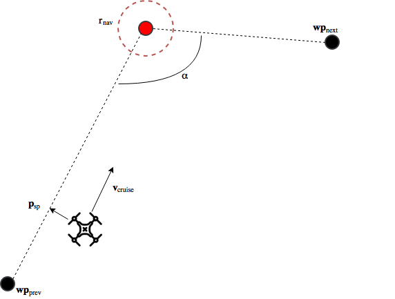
In auto mode the vehicle always follows a straight line from the previous waypoint to the current target.
 .
.
$$\mathbf{wp}_{prev}$$ is the previous waypoint that either was already passed or is the position at the time when the new target waypoint was received, but no previous waypoint provided. The setpoint during line tracking can be split into two components:
- position setpoint $$\mathbf{p}_{sp}$$: it is the pose on the track closest to vehicle position
- velocity setpoint $$\mathbf{v}_{cruise}$$: it the desired velocity along the track
The cruise speed of $$\mathbf{v}{cruise}$$ is by default MPC_XY_CRUISE. However, if the target waypoint (red circle) is close to the previous waypoint, the
cruise speed will be adjusted accordingly. To reach the cruise speed, $$\mathbf{v}{cruise}$$ will accelerate with MPC_ACC_HOR.
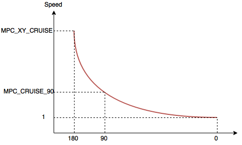
When the vehicle is 1.5 x MPC_XY_CRUISE in front of the target waypoint, the vehicle will start to decelerate to a target speed that depends on the angle $$\alpha$$. The function used for the mapping
from angle to target speed is an exponential function of the form $$a \times b^{x} + c$$:
 .
.
At an angle of 180 degrees, which corresponds to a straight line from $$\mathbf{wp}{prev}$$ to $$\mathbf{wp}{next}$$ with the target waypoint somewhere in between, the target speed at the target waypoint
will be MPC_XY_CRUISE. If the angle is 0 degrees, which correponds to having $$\mathbf{wp}{next}$$ on the line $$\mathbf{wp}{prev}$$ to target waypoint, then the target speed is set to a minimum speed of 1 m/s.
If the angle is 90 degrees, the target speed is set to MPC_CRUISE_90. All other possible angles are mapped to the target speed from the same exponential function.
If there is no $$\mathbf{wp}_{next}$$ present, then the vehicle will just decelerate to zero cruise speed.
A target waypoint is considered reached once the vehicle is within the acceptance radius $$r{rad}$$ that is parametrized by NAV_ACC_RAD. In addition, the vehicle also has to reach the desired altitude (theshold NAV_MC_ALT_RAD) and the desired yaw (threshold MIS_YAW_ERR). Once the vehicle enters that circle, the waypoints will update. $$\mathbf{wp}{next}$$ will become the new target waypoint, $$\mathbf{wp}{prev}$$ will assume the old target waypoint and a new $$\mathbf{wp}{next}$$ will be added.